Cooling modularity is not achieved by placing a pump and a heat exchanger on a skid. It is achieved when temperature, flow, pressure, water quality and control behavior remain coordinated across every connection.
The starting point is the computing equipment. Establish how much heat is removed by air and how much by liquid, the allowable operating envelope and the behavior during an interruption. Equipment vendors may specify different limits, even when their racks have similar electrical ratings. A facility should not inherit a single convenient temperature assumption that none of its intended equipment has actually accepted.
Follow the heat, not the product label
For an air-cooled installation, the path includes rack airflow, containment, room cooling and outdoor heat rejection. For direct-to-chip liquid cooling, it may include cold plates, rack manifolds, technology cooling loops, coolant distribution units and a facility water system. Residual air cooling often remains necessary. Liquid cooling therefore changes the balance of plant; it does not automatically remove the need for room environmental control.
ASHRAE Technical Committee 9.9 publishes guidance for data processing environments, including thermal guidance relevant to liquid cooling. Treat it as a basis for informed coordination alongside the actual equipment requirements. Temperature class terminology is useful only when the parties agree which fluid, measurement location and operating condition it describes.
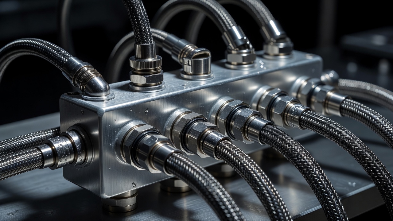
Make the hydraulic hand-off explicit
A coolant distribution unit, commonly called a CDU, can separate technology coolant from facility water through a heat exchanger. That separation does not eliminate coordination. Available facility-water temperatures and flow must support the required technology-side conditions at the relevant load. Heat-exchanger approach temperature and pump energy belong in the design discussion, not just in a supplier's internal calculation.
State allowable working pressure, differential pressure, water chemistry, filtration, materials and flushing requirements. Confirm whether the connecting systems use compatible seals and corrosion-control practices. Construction debris introduced during a later tie-in can undermine a carefully prepared loop. A modular connection should be both mechanically repeatable and supported by a controlled cleanliness procedure.
Use clear ownership for filling, sampling, leak checks and fluid disposal. A quick-disconnect fitting reduces some maintenance steps but does not make a connection risk-free. Access space, hose routing, strain relief and protection from accidental impact still matter. Operators need to know what liquid remains trapped when a section is isolated and how it will be contained safely.
Control the change, not just the setpoint
Multiple modules can each behave correctly in isolation yet interact poorly when connected. Pump pressure controls may compete; valves may hunt; a common sensor may become a hidden dependency. Specify which controller owns each operating objective and how local equipment behaves when communication is lost. Alarm priorities should make an abnormal condition intelligible rather than create an unmanageable cascade.
Part-load operation deserves the same attention as peak duty. The first phase may operate far below the eventual system design point. Check minimum flow, stable control ranges and the sequencing of plant. Where variable-speed systems are used, consider the actual hydraulic arrangement rather than assuming speed reduction always produces the intended energy benefit.
A future connection is also a future cleanliness event.— Teammeteortrelum editorial principle, The purpose of this journal
| Approach | Potential strength | Interface to resolve |
|---|---|---|
| Contained air cooling | Familiar rack service model | Airflow and residual bypass |
| Direct-to-chip cooling | Heat capture close to processors | CDU duty and remaining air load |
| Immersion cooling | Liquid contact around equipment | Equipment compatibility and handling |
Design the outdoor consequence
Heat rejection depends on climate, water availability, acoustics, footprint and the chosen operating temperatures. Dry coolers, chillers and evaporative systems offer different compromises. A campus that adds indoor cooling modules without reserving outdoor plant space may discover that its apparent modularity stops at the building wall. Review access, separation distances and maintenance lifting routes for the final arrangement.
Heat reuse is another interface rather than a guaranteed benefit. A receiving network needs compatible temperatures, dependable demand, contractual arrangements and a way to manage periods when it cannot accept heat. The European Code of Conduct for Data Centre Energy Efficiency provides a useful reference for energy management practices. It does not substitute for a site-specific assessment of whether heat recovery is technically and commercially workable.
Prove recovery as well as steady operation
Commissioning should examine leak detection, pump changeover, loss of communication, isolation and restart. Agree how representative thermal loads will be provided and which conditions can only be simulated. Record limitations honestly. Where temporary hoses or bypasses are used, establish how they differ from the permanent configuration.
The Open Compute Project's Advanced Cooling Solutions work provides a further industry reference for emerging interfaces and practices. CIBSE also offers building-services guidance relevant to plant and operation. Neither removes the need to coordinate actual vendor limits. A maintainable cooling module is one that can be connected, observed, isolated and replaced without leaving the rest of the thermal path undefined.